


Mega 2560 R3 Development Board Compatible with Arduino
Mega 2560 compatible with Arduino It is a clone of the latest version of Arduino Mega. The product also includes a USB cable for computer connection. For the more affordable...
Vendor:
Robotistan
SKU:
11604
- $25.44
-
- $25.44
- Unit price
- per

Free Shipping
Free standard shipping on orders over $100
Free Returns
Learn More.
Mega 2560 compatible with Arduino
- It is a clone of the latest version of Arduino Mega. The product also includes a USB cable for computer connection. For the more affordable ch340 model. As Robotistan, we recommend that you always use original products.
Product Content:
Arduino Mega 2560 (Klon)
The Arduino Mega 2560 is a microcontroller board based on the Atmega2560. It has 54 digital I/O pins (15 of which are PWM outputs), 16 analog inputs, 4 UART (hardware serial ports), a 16Mhz crystal, a USB socket, a power socket, an ICSP connector, and a reset button. On the board, you'll find everything you need to run the microcontroller. It is easily connected to a computer using a USB cable and can be powered by an adapter or a battery.
To load programs and communicate with computers, it has an Atmega16u2 (Rev 2 had an Atmega8u2) usb-serial converter. Many improvements have been made to the Mega rev 3 version to make it easier to use and more stable than the rev 2 version.
Technicial Specifications:
- Microcontroller Atmega2560
- Operating Voltage 5V
- Input Voltage (recommended) 7-12V
- Input Voltage (limit) 6-20V
- Digital I/O Pins 54 (15 of them PWM outputs)
- Analog Input Pins 16
- Current per I/O 40 mA
- Current for 3.3V Output 50 mA
- Flash Memory 256 KB (Atmega2560) 8 KB is used by the bootloader
- SRAM 8 KB (ATmega2560)
- EEPROM 4KB (ATmega2560)
- Clock Speed 16MHz
- Length 101.6mm
- Width 53.4mm
- Weight 36g
Strength:
Arduino Mega can get its power via usb or external power supply. The external power source can be either an AC-DC adapter or a battery. The adapter can be connected from the 2.1mm center-positive power socket on the board. The battery can be connected via the GND and Vin pins on the board. It is not necessary to have the USB constantly connected for the card to work. The card can only be powered by adapter or battery. In this way, the card can be operated independently from the computer. It can be used as an external power supply between 6-20V. However, these values are limit values. The recommended external supply for the board is between 7-12V. The operating voltage of the Mega board's microcontroller is 5V. The voltage between 7 and 12 volts applied to the Vin pin or power socket is reduced to 5 volts by the board's voltage regulator and distributed to the board.
Power pins are as follows:
VIN: Voltage input pin between 7-12V when using external power supply.
5V: 5V is pin outputs 5V from the regulator. If the board only works over usb (5V), 5V from usb is output directly over this pin. If power is supplied to the board via Vin (7-12V) or power socket (7-12V), 5V from the regulator is output directly over this pin.
3V3: It is the output pin of the 3.3V regulator on the board. Max. It can output 50mA.
GND: Ground pins.
Memory: Atmega2560 has 256 KB flash memory (8 KB is used by bootloader). It has 8 KB SRAM and 4 KB EEPROM.
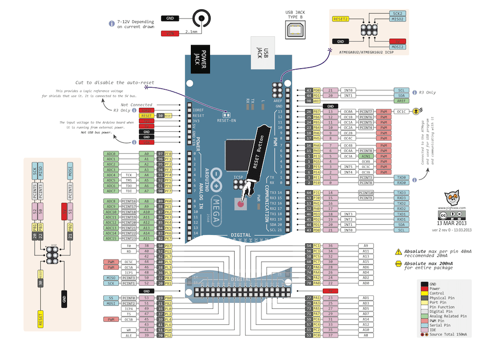
Input and Output:
All 54 digital pins on the Mega can be used as inputs or outputs. There are also 16 analog input pins. These analog input pins can also be used as digital inputs and outputs. on the other hands, there are 70 digital input and output pins on the board. The logic level of all these pins is 5V. Each pin max. It works with 40mA input and output current. In addition, some pins have different properties. Special pins are as follows.
- Serial: 0 (RX) and 1 (TX), Serial1: 19 (RX) and 18 (TX), Serial2: 17 (RX) and 16 (TX), Serial3: 15 (RX) and 14 (TX): TTL Serial is used for data reception (RX) and transmission (TX). Pins 0 and 1 are directly connected to the board's Atmega16u2 usb-serial converters. In other words, these pins are also used when the code is uploaded from the computer to the card or when mass transmission occurs between the computer and the mega. As a result, it is best not to use these pins unless absolutely necessary to avoid errors when uploading or transmitting the code to the card.
- 2 (interrupt 0), 3 (interrupt 1), 18 (interrupt 5), 19 (interrupt 4), 20 (interrupt 3), 21 (interrupt 2): These pins can be used as rising edge, falling edge, or change interrupt pins.
- PWM output pins :2-13 and 44-46: 8-bit resolution can be used.
- SPI, 53 (SS), 51 (MOSI), 50 (MISO), 52 (SCK): These are SPI communication pins.
- LED, 13: An internal LED is connected to Mega via pin 13. When the pin is set to HIGH, the led turns on; when it is set to LOW, the led turns off.
- (A0-A15): Mega has 16 analog input pins with 10-bit resolution (A0-A15). These pins are suitable for digital input and output. The pins' measuring range is 0-5V. Lower and upper limits can be increased and decreased using the AREF pin and the AnalogReference() function.
- I2C: pin 20 or SDA and pin 21 or SCL: These pins are used for I2C communication.
- AREF: Reference pin for analog input.
- Reset: When the microcontroller is reset, this pin is set to LOW. Reset operation can also be done with the Reset Button on the card.
Communication:
To communicate with a computer, another Arduino, or a microcontroller, the Arduino Mega has several options. The Atmega2560 has four hardware UART TTL (5V) serial communication ports.The card's Atmega16u2 usb-serial converter establishes a bridge between the Atmega2560 and the computer by opening a virtual com port on the computer. The Arduino computer program, which includes a serial monitor, allows text-based information to be sent and received between the arduino and the computer. The RX and TX leds on the card will light up when there is USB communication between the usb-serial converter and the computer.
There are 4 serial ports on the Mega as hardware. However, this number can be increased in software with the SoftwareSerial library.
Atmega2560 also provides I2C and SPI ports. The Wire library that comes with the Arduino computer program is used to use I2C, and the SPI library is used to provide SPI communication.
Programming:
Arduino Mega board is programmed with Arduino computer program (Arduino IDE).You can begin programming by selecting Arduino Mega from the program's Tools > Board tab. You can find more information on the reference and basic functions pages. On the Arduino Mega, a special software called bootloader is installed on the Atmega2560. This eliminates the need for an additional programmer when programming the card. The original STK500 protocol is used for communication.
By bypassing the bootloader software, the board can be programmed directly via the ICSP header of the microcontroller with the ISP programmer (Reference).
The source software in the Atmega16u2 is open source, as is the bootloader software. This software is also known as the DFU bootloader. This software can be reinstalled using the FLIP software (Windows) or the DFU programmer from Atmel (Mac OS X and Linux). It can also be programmed with an ISP programmer in 16u2 like the Atmega2560. The software in both the Atmega2560 and the 16u2 is always the most recent version. As a result, unless absolutely necessary, you should not change this software.
USB Overcurrent Protection:
The resettable fuse on the Arduino Mega protects the USB port of the computer from short circuits or excessive current consumption. When the card draws more than 500mA current through the computer usb port, the card automatically cuts off the power it receives from the usb for protection. When the overcurrent condition or short circuit is eliminated, the fuse returns to its normal position and reconnects.
Get more information about:
Related Products
Robotistan
Example product title
- $25.44
-
- $25.44
- Unit price
- per
Robotistan
Example product title
- $25.44
-
- $25.44
- Unit price
- per
Robotistan
Example product title
- $25.44
-
- $25.44
- Unit price
- per
Robotistan
Example product title
- $25.44
-
- $25.44
- Unit price
- per
Robotistan
Example product title
- $25.44
-
- $25.44
- Unit price
- per
Robotistan
Example product title
- $25.44
-
- $25.44
- Unit price
- per
Robotistan
Example product title
- $25.44
-
- $25.44
- Unit price
- per
Robotistan
Example product title
- $25.44
-
- $25.44
- Unit price
- per
Robotistan
Example product title
- $25.44
-
- $25.44
- Unit price
- per
Robotistan
Example product title
- $25.44
-
- $25.44
- Unit price
- per
Recently Viewed Products
Robotistan
Example product title
- $25.44
-
- $25.44
- Unit price
- per
Robotistan
Example product title
- $25.44
-
- $25.44
- Unit price
- per
Robotistan
Example product title
- $25.44
-
- $25.44
- Unit price
- per
Robotistan
Example product title
- $25.44
-
- $25.44
- Unit price
- per
Robotistan
Example product title
- $25.44
-
- $25.44
- Unit price
- per
Robotistan
Example product title
- $25.44
-
- $25.44
- Unit price
- per
Robotistan
Example product title
- $25.44
-
- $25.44
- Unit price
- per
Robotistan
Example product title
- $25.44
-
- $25.44
- Unit price
- per
Robotistan
Example product title
- $25.44
-
- $25.44
- Unit price
- per
Robotistan
Example product title
- $25.44
-
- $25.44
- Unit price
- per
- Choosing a selection results in a full page refresh.
