


 on Robotistan Maker Store")
 on Robotistan Maker Store")
Nano 328 Development Board Compatible with Arduino (Wih USB Cable)
Arduino nano with usb cable Not CH340 Product content: Arduino Nano Mini-B Usb Cable The Arduino Nano is a microcontroller board based on the Atmega328. It has 14 digital I/O...
Vendor:
Robotistan
SKU:
11610
- $9.22
-
$11.00 - $9.22
- Unit price
- per

Free Shipping
Free standard shipping on orders over $100
Free Returns
Learn More.
Arduino nano with usb cable Not CH340
Product content:
- Arduino Nano
- Mini-B Usb Cable
The Arduino Nano is a microcontroller board based on the Atmega328. It has 14 digital I/O pins (6 of which are PWM outputs), 8 analog inputs, a 16Mhz crystal, a USB socket, an ICSP connector, and a reset button. On the board, you'll find everything you need to run the microcontroller. It is easily connected to a computer using a USB cable and can be powered by an adapter or a battery.
- Nano: It has FTDI FT232 usb-serial converter on it to load programs and make computer communication.
Technicial Specifications:
- Microcontroller ATmega328
- Operating Voltage 5V
- Input Voltage (recommended) 7-12V
- Input Voltage (limit) 6-20V
- Digital I/O Pins 14 (6 of them PWM outputs)
- Analog Input Pins 8
- Current per I/O 40 mA
- Current for 3.3V Output 50 mA
- Flash Memory 32 KB (ATmega328) Up to 2 KB is used by the bootloader
- SRAM 2KB (ATmega328)
- EEPROM 1KB (ATmega328)
- Clock Speed 16MHz
- Length 45mm
- Width 18mm
- Weight 5g
Power:
Arduino Nano can get its power via usb or external power supply. The external power source can be either an AC-DC adapter or a battery. The adapter and battery can be connected via the GND and Vin pins on the board. Arduino nano is not necessary to have the USB constantly connected for the card to work. The card can only be powered by adapter or battery. In this way, the card can be operated independently from the computer.
Arduino Nano is can be used as an external power supply ranging from 6 to 20 volts. These, however, are upper bounds. The board's recommended external power supply range is 7-12V. Because the board's regulator may not function properly at voltages lower than 7V. It can also overheat at voltages greater than 12V.
The operating voltage of the microcontroller on the nano board is 5V. The voltage between 7-12V, which is given over the Vin pin or power socket, is reduced to 5V with the voltage regulator on the board and distributed to the board.
The power pins are as follows:
- VIN: Voltage input pin between 7-12V when using external power supply.
- 5V: This pin outputs 5V from the regulator. If the board only works over usb (5V), 5V from usb is output directly over this pin. At the same time, 5V input can be made through this pin. If the power is supplied to the board via Vin (7-12V), 5V from the regulator is directly output from this pin.
- 3V3: It is the output pin of the 3.3V regulator on the board. Max. It can output 50mA.
- GND: Ground pins.
Memory:
The Atmega328 has 32 KB of flash memory (about 2 KB is used by the bootloader). Arduino nano has 2 KB SRAM and 1 KB EEPROM.
Input and Output:
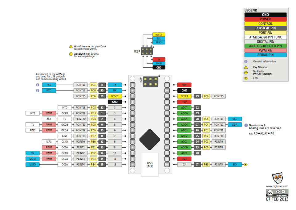
The Nano's 14 digital pins can all be used as inputs or outputs. There are 8 analog input pins as well. These analog input pins can be used as digital inputs and outputs as well. In other words, the board has 20 digital input and output pins. All of these pins have a logic level of 5V. Each pin has a maximum capacity. It has an input and output current of 40mA. Furthermore, some pins have unique properties. The following are special pins.
- Serial Communication, 0 (RX) and 1 (TX): TTL Used to receive (RX) and transmit (TX) serial data. These pins are directly connected to the FT232 usb-serial converter on the board. In other words, these pins are also used when uploading code from the computer to the card or when making mutual communication between the computer and the nano. Therefore, it is useful not to use these pins unless it is necessary to avoid errors while uploading code to the card or communicating.
- External Interrupt, 2 (interrupt 0) and 3 (interrupt 1): These pins can be used as rising edge, falling edge, or change interrupt pins. For detailed information, you can check the attachInterrupt() function page.
- PWM, 3,5,6,9,10 and 11: 8-bit resolution can be used as PWM output pins.
- SPI, 10 (SS), 11 (MOSI), 12 (MISO), 13 (SCK): These pins are used for SPI communication.
- LED, 13: There is an internal LED connected to pin 13 via Nano. When the pin is set to HIGH, the led will turn on, and when the pin is set to LOW, the led will turn off.
- Analog, A0-A7: Nano has 8 analog input pins with 10-bit resolution. These pins can be used in digital input and output. The measuring range of the pins is 0-5V. By using AREF pin and analogReference() function, lower limit can be increased and upper limit can be lowered.
- I2C, A4 or SDA pin and A5 or SCL pin: These pins are used for I2C communication.,
- I2C, A4 or SDA pin and A5 or SCL pin: These pins are used for I2C communication.
- Reset: When the microcontroller is reset, this pin is set to LOW. Reset operation can also be done with the Reset Button on the card.
- You can review the pin mapping page between Arduino nano and Atmega328.
Communication:
There are several different options for Arduino Nano to communicate with a computer, another arduino or microcontroller. Atmega328 offers UART TTL (5V) serial communication via 0 (RX) and 1 (TX) pins. FT232 usb-serial converter on the card opens a virtual com port on the computer and establishes a bridge between the Atmega328 and the computer. Arduino computer program allows text-based information to be sent and received between the arduino and the computer with the serial monitor it contains. When there is communication between the usb-serial converter and the computer via usb, the RX and TX leds on the card will light up.
As far as hardware is concerned, the nano has only one serial port. This number, however, can be increased in software using the SoftwareSerial library.
Atmega328 also provides I2C and SPI ports. Wire library that comes with the Arduino computer program is used to use I2C, and the SPI library is used to provide SPI communication.
Programming:
Arduino Nano board is programmed with the Arduino computer program (Arduino IDE). You can start programming by selecting Arduino Nano under Tools > Board tab in the program. For detailed information, you can review the reference and basic functions page. A special software called bootloader is installed on the Atmega328 on the Arduino Nano. In this way, you do not need to use an extra programmer while programming the card. Communication is provided with the original STK500 protocol.
By omitting the bootloader software, the board can be programmed directly with the ISP programmer via the ICSP header of the microcontroller (Reference).
Documents:
Related Products
Robotistan
Example product title
- $9.22
-
$11.00 - $9.22
- Unit price
- per
Robotistan
Example product title
- $9.22
-
$11.00 - $9.22
- Unit price
- per
Robotistan
Example product title
- $9.22
-
$11.00 - $9.22
- Unit price
- per
Robotistan
Example product title
- $9.22
-
$11.00 - $9.22
- Unit price
- per
Robotistan
Example product title
- $9.22
-
$11.00 - $9.22
- Unit price
- per
Robotistan
Example product title
- $9.22
-
$11.00 - $9.22
- Unit price
- per
Robotistan
Example product title
- $9.22
-
$11.00 - $9.22
- Unit price
- per
Robotistan
Example product title
- $9.22
-
$11.00 - $9.22
- Unit price
- per
Robotistan
Example product title
- $9.22
-
$11.00 - $9.22
- Unit price
- per
Robotistan
Example product title
- $9.22
-
$11.00 - $9.22
- Unit price
- per
Recently Viewed Products
Robotistan
Example product title
- $9.22
-
$11.00 - $9.22
- Unit price
- per
Robotistan
Example product title
- $9.22
-
$11.00 - $9.22
- Unit price
- per
Robotistan
Example product title
- $9.22
-
$11.00 - $9.22
- Unit price
- per
Robotistan
Example product title
- $9.22
-
$11.00 - $9.22
- Unit price
- per
Robotistan
Example product title
- $9.22
-
$11.00 - $9.22
- Unit price
- per
Robotistan
Example product title
- $9.22
-
$11.00 - $9.22
- Unit price
- per
Robotistan
Example product title
- $9.22
-
$11.00 - $9.22
- Unit price
- per
Robotistan
Example product title
- $9.22
-
$11.00 - $9.22
- Unit price
- per
Robotistan
Example product title
- $9.22
-
$11.00 - $9.22
- Unit price
- per
Robotistan
Example product title
- $9.22
-
$11.00 - $9.22
- Unit price
- per
- Choosing a selection results in a full page refresh.
